Note: This post was moved from my previous website and is in need of review. A dump of code and wiring diagrams for an LED cube and the, very similarly wired, LED Matrix, including the tetris code, can be found on GitHub: arduino-led-cube-and-matrix. (September 2015)
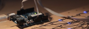
Almost two years ago now I started planning and building a custom LED matrix to be controlled by my Arduino Duemilanove which sports an ATMega328 microprocessor. I used four Max7221 chips that I knew from a previous project and daisy-chained them to control the four 8x8 sections of my 16x16 matrix.
Arduino is an awesome rapid development and prototyping platform for learning to use and appreciate microcontrollers. Their boards contain a USB controller for power supply and programming from a PC, some status LEDs and pin sockets for interfacing to external hardware, all at a very affordable price. They have recently moved to the Arduino Uno (different USB controller, but still based on the ATMega 328) and version 1.0 of the software. Once I package my code as a library I’ll also check that it’s compatible with the new version.
Hardware
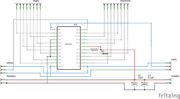
I use four Max7221 Display Controllers for 256 LEDs in a 16x16 matrix pattern. The Max7219 is almost identical and slightly cheaper for this kind of application. These ICs are awesome because they take a lot of work off the microcontroller and, more importantly, the wiring and logic design. You can daisy-chain up to eight (or even more) of them to theoretically make a display twice as big as this. The interface takes up only three output pins on the Arduino. They were meant for driving eight seven segment displays each but can be configured with custom patterns instead – giving eight rows and columns. Data is shifted through the devices on the common clock, each contains a 16 bit shift register from which the address (one matrix row or special function) and data (a control value or on/off information for each LED in the row) is read on the Load signal. The data for each row is stored in internal registers, and then they operate by the persistence of vision principle. That is, each row of the matrix is flashed in turn, so fast that we think they’re all on at the same time. This allows them to connect to 64 LEDs with only 16 wires. Again, if in doubt have a look at the data sheet – it’s very helpful.
The only additional components are two decoupling capacitors (10µF and 0.1µF) and a single current limiting resistor for the LEDs. The resistor is defined by the LEDs’ forward voltage and current, as described in a table in the datasheet. I built the four control units on separate boards: They’re connected by a five line bus, sending the data out (DOUT) from the first chip to the data in (DIN) of the next one and so on, as well as providing the common bus clock, load signal and the power supply to all units.
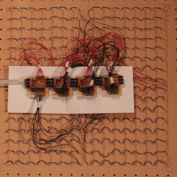
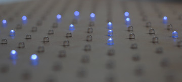
I should note that the whole thing is by no means a polished product, it’s much more of an experimental proof-of-concept setup and the wiring on the back looks very unprofessional now.
Interfacing
I initially wrote my own library for controlling such a matrix, but later I switched over to the excellent LedControl library. I wrote a class (LedDisplay) that extends it in order to map my 16x16 display onto the four 8x8 matrices controlled by LedControl. All data is stored locally as it is updated by the program. Pushing out the serial data is slow, hence it is only done on explixit request via the pushData() method. Here’s an overview:
//Initialize pins (clock, data, load/CS, connected to the first device)
LedDisplay Disp = new LedDisplay(10, 11, 12);

//turn all LEDs off. There is also allOn();
Disp.allOff();

//turn on one LED. Coordinates are x, y (1-based from bottom left)
Disp.setState( 1, 2, 1 );

//shift all data out to the ICs
Disp.pushData();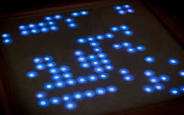
Conway’s Game of Life
 Kristian Hentschel